Prompt-Driven Walkthrough: Smart Dimensions, Reference Points, Save Bodies & Center Marks
This tutorial reproduces a live session that was run end-to-end against
SolidWorks 3DEXPERIENCE R2026x through the MCP server. Every screenshot on
this page was captured with the export_image tool during that run — nothing is
mocked.
It covers four capabilities, three of them added in v1.2.0:
| Tool | What it does | Added |
|---|---|---|
add_sketch_dimension |
Drives a rough sketch to exact size (linear + diameter) | earlier |
create_reference_point |
Reference point on an edge (along_curve) or face centroid (face_center) |
1.2.0 |
save_body_as_part |
Extracts one solid body of a multibody part to a standalone .sldprt |
1.2.0 |
auto_center_marks |
Runs SolidWorks' automatic centre-mark insertion on a drawing view | 1.2.0 |
You drive the whole thing with plain-language prompts — the exact text is in each section. The assistant translates each prompt into the MCP tool calls shown underneath it.
What you need
- SolidWorks running, COM-accessible, no documents open.
- The
solidworks-mcpserver connected to your MCP client (Claude Code / Claude Desktop / VS Code). If you just restarted SolidWorks, reconnect the server first — a stale COM handle causesNo part template configured/No active modelerrors (theCLAUDE.mdtroubleshooting runbook at the repo root covers this as "stale COM handle"). - A scratch folder that already exists, e.g.
C:\Temp\wave3_demo\. The tools do not create the parent directory —save_body_as_partrefuses a missing one on purpose.
One instruction that saves you a support ticket
Put "stop and show me the tool call and error if anything fails" in every
prompt. The tools return structured status / message payloads; surfacing
them verbatim is how you debug a live CAD session.
Scenario A — Smart-dimensioned bracket → reference points → save body
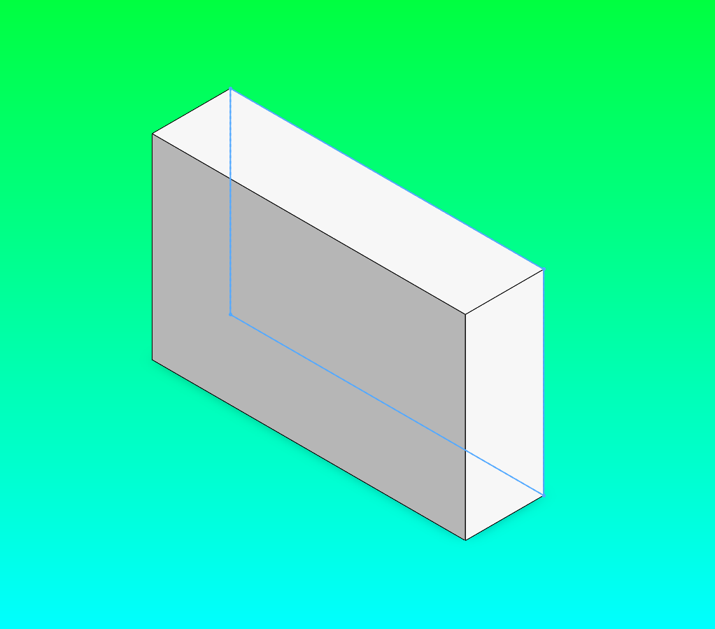
Step A1 — Build a bracket from a rough sketch, then smart-dimension it
The point of this step: you sketch approximately, then let dimensions snap the geometry to the real numbers. That is how a parametric sketch is meant to be built.
Prompt:
Create a new part in mm. On the Front plane, sketch a rectangle roughly
76 x 46 mm using four lines starting at the origin. Then add smart sketch
dimensions to drive it to exactly 80 mm wide and 50 mm tall. Exit the sketch
and extrude it 20 mm. Show me each tool call and its result. Stop on any error.
Tool calls the assistant makes:
| # | Tool | Key arguments | Result |
|---|---|---|---|
| 1 | create_part |
name="Wave3Bracket", units="mm" |
Part45 |
| 2 | create_sketch |
plane="Front" |
Sketch1 |
| 3 | add_line ×4 |
(0,0)->(76,0), (76,0)->(76,46), (76,46)->(0,46), (0,46)->(0,0) |
Line_1 … Line_4 |
| 4 | add_sketch_dimension |
entity1="Line_1", dimension_type="linear", value=80 |
Dimension_5 — "Added linear dimension of 80.0mm to Line_1" |
| 5 | add_sketch_dimension |
entity1="Line_2", dimension_type="linear", value=50 |
Dimension_6 — "…50.0mm to Line_2" |
| 6 | exit_sketch |
— | ok |
| 7 | create_extrusion |
sketch_name="Sketch1", depth=20 |
Boss-Extrude1 |
add_sketch_dimension only accepts entity IDs from line/arc/circle/spline/centerline
It cannot dimension a Rectangle_1 returned by add_rectangle — that tool
hands back one ID for the whole rectangle, not its four edges. Build
dimensionable rectangles with four add_line calls so you get
Line_1 … Line_4 back. Linear values are millimetres; angular values are
degrees.
Step A2 — Add two reference points
create_reference_point has two modes. Both resolve their location with a
coordinate pick, so the (x, y, z) you give in millimetres must actually lie
on the target edge or face.
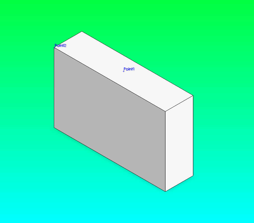
Prompt:
On this bracket, add a reference point at the centre of the top face
(the face at y = 50), and another at the midpoint of the top-back edge.
Use face_center mode for the first and along_curve at 50 percent for the
second. Report the feature count before and after each.
Tool calls:
| # | Tool | Key arguments | Result |
|---|---|---|---|
| 1 | create_reference_point |
mode="face_center", x=40, y=50, z=10 |
"Created a reference point at a face centre" — features 19 → 20 |
| 2 | create_reference_point |
mode="along_curve", x=40, y=50, z=20, percent=50 |
"Created a reference point at 50.0% along a curve" — features 20 → 21 |
along_curve also takes distance (mm from the edge start) instead of
percent — give exactly one. InsertReferencePoint always returns a feature, so
the tool confirms success by the feature tree growing, not by the API return.
Origin-plane picks fail on SolidWorks 2026
A coordinate pick where x = 0 or z = 0 resolves the reference plane
at the origin instead of your edge/face, and the tool reports
"No edge/face found at …". That is why the prompt targets the top face at
y = 50 and an edge at z = 20 — both clear of the origin planes. Pick a
coordinate a few millimetres off any origin plane.
Step A3 — Extract the body to its own part
Prompt:
Save the solid body of this bracket to C:\Temp\wave3_demo\bracket_body.sldprt.
First try a body name I know is wrong ("NotARealBody") so I can see the error,
then use the real one.
Tool calls:
| # | Tool | Key arguments | Result |
|---|---|---|---|
| 1 | save_body_as_part |
body_name="NotARealBody", file_path="C:\Temp\wave3_demo\bracket_body.sldprt" |
error — "Body 'NotARealBody' not found. Solid bodies: Boss-Extrude1" |
| 2 | save_body_as_part |
body_name="Boss-Extrude1", file_path="C:\Temp\wave3_demo\bracket_body.sldprt" |
"Saved body Boss-Extrude1 …" — feature="Save Bodies1", solid_bodies=["Boss-Extrude1"] |
The wrong-name call is not a trick — the response always lists every solid
body it found, so a bad guess tells you the real options. Success is confirmed by
the file existing on disk afterwards (here: a ~53 KB .sldprt).
Save Bodies opens a linked assembly
SolidWorks' Save Bodies feature also creates and opens a linked assembly of
the split bodies (standard behaviour — the "Create assembly" box). After the
call you will have an extra Assem… document open. Close it without saving;
add "then close any assembly that Save Bodies opened" to the prompt if you
want the assistant to tidy up.
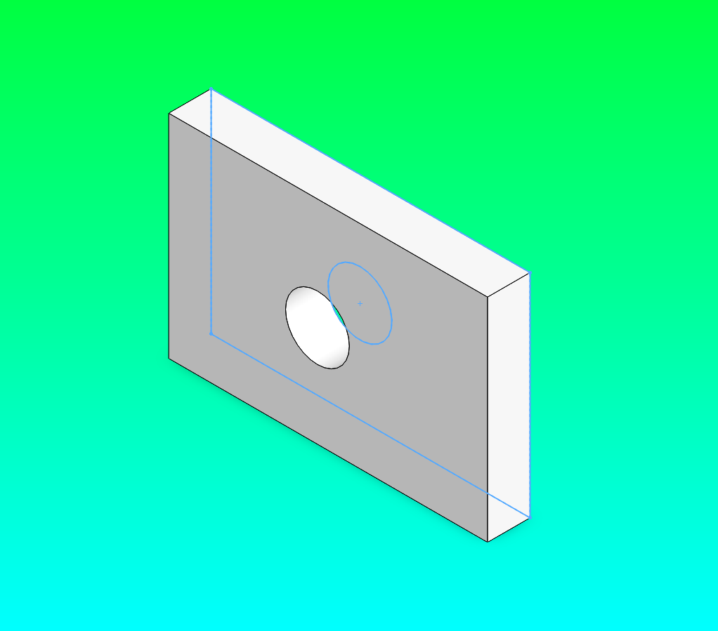
Scenario B — Smart-dimensioned plate with a hole → drawing → centre marks
Step B1 — Plate with a through hole, fully smart-dimensioned
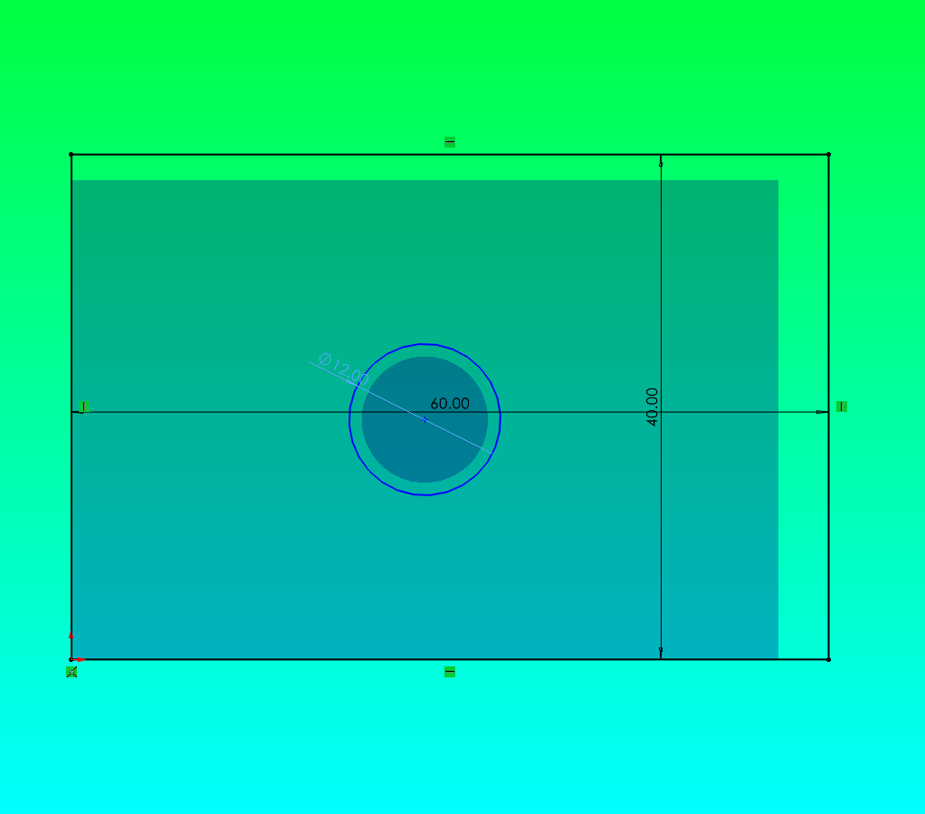
Prompt:
New part in mm. On the Front plane, draw a rough rectangle about 56 x 38 mm
from the origin with four lines, and a circle of radius 5 near the middle at
about (28, 19). Smart-dimension it: rectangle to 60 x 40 mm, and the circle to
a 12 mm diameter. Exit the sketch and extrude 8 mm so the circle leaves a
through hole. Then save it to C:\Temp\wave3_demo\plate.sldprt.
Tool calls:
| # | Tool | Key arguments | Result |
|---|---|---|---|
| 1 | create_part |
units="mm" |
Part47 |
| 2 | create_sketch |
plane="Front" |
Sketch1 |
| 3 | add_line ×4 |
rough 56 × 38 rectangle | Line_1 … Line_4 |
| 4 | add_circle |
center_x=28, center_y=19, radius=5 |
Circle_5 |
| 5 | add_sketch_dimension |
Line_1, linear, 60 |
Dimension_6 |
| 6 | add_sketch_dimension |
Line_2, linear, 40 |
Dimension_7 |
| 7 | add_sketch_dimension |
entity1="Circle_5", dimension_type="diameter", value=12 |
Dimension_8 — "Added diameter dimension of 12.0mm to Circle_5" |
| 8 | exit_sketch → create_extrusion |
depth=8 |
Boss-Extrude1 |
| 9 | save_part |
file_path="C:\Temp\wave3_demo\plate.sldprt" |
saved |
Putting the rectangle and the circle in one profile means a single
create_extrusion leaves a clean through hole — no cut feature needed.
(create_cut is not wired to live COM yet on this build.)
The diameter path uses SolidWorks' dedicated AddDiameterDimension2 API, which
stays non-interactive — no Modify dialog. radial works the same way for a
radius.
Step B2 — Make a drawing
Prompt:
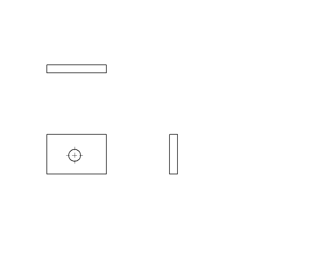
Create a drawing, then lay out the three standard views of
C:\Temp\wave3_demo\plate.sldprt on it at 1:1.
Tool calls:
| # | Tool | Key arguments | Result |
|---|---|---|---|
| 1 | create_drawing |
name="Wave3Plate2Drawing" |
Draw13 - Sheet1 |
| 2 | create_technical_drawing |
model_file="C:\Temp\wave3_demo\plate.sldprt", auto_populate_views=true, scale="1:1" |
["Drawing View1", "Drawing View2", "Drawing View3"], projection="third_angle" |
create_technical_drawing needs a drawing to already exist
It lays views onto the active drawing sheet; it does not create the
document. Always create_drawing first, or you get
"requires a drawing document … Call create_drawing first".
Step B3 — Auto-insert centre marks
Prompt:
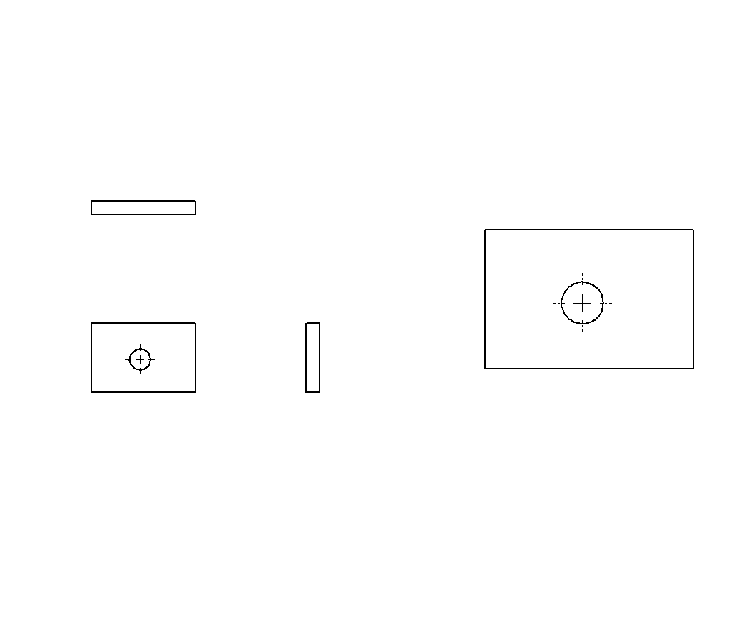
Run auto centre marks on Drawing View1 for holes and slots, and report the
before/after count. Then add a plain front view of the plate and run it on
that view too.
Tool calls:
| # | Tool | Key arguments | Result |
|---|---|---|---|
| 1 | auto_center_marks |
view_name="Drawing View1", mark_holes=true, mark_slots=true |
success — center_marks_before=0, center_marks_after=0, center_marks_added=0 |
| 2 | create_drawing_view |
view_type="orthographic", orientation="front", position_x=320, position_y=120 |
Drawing View4 |
| 3 | auto_center_marks |
view_name="Drawing View4", … |
success — same 0 / 0 / 0 shape; the crosshair is inserted (see image) |
Why the reported count is 0 even when a mark appears
auto_center_marks reads IView::GetCenterMarkCount() before and after and
reports the delta, because AutoInsertCenterMarks returns no count of its
own. On SolidWorks 3DEXPERIENCE R2026x that accessor returns 0 regardless
of the marks actually present, so center_marks_added understates reality.
The tool's contract already treats added: 0 as success — "the view may
have no un-marked holes". Trust the drawing, not the number, on this build
(a count-readback fix is tracked in the issue tracker). On drawings whose
template does not auto-insert marks on view creation, this tool is how
you add them in bulk.
Cleanup
Prompt:
close_model acts on the active document. If several are open (part +
drawing, or a Save Bodies assembly), the assistant calls activate_document
then close_model per document, or loops close_model until
list_open_documents returns empty. Nothing in this tutorial writes to your real
work — the only files created are under your scratch folder.
What is and isn't live today
| Capability | Live via MCP? |
|---|---|
add_sketch_dimension — linear / radial / diameter / angular |
✅ |
create_reference_point — along_curve, face_center |
✅ |
save_body_as_part |
✅ (also opens a linked assembly) |
auto_center_marks — insertion |
✅ (count read-back unreliable on R2026x) |
add_dimension / auto_dimension_view — drawing dimensions |
❌ not wired to COM — sketch dimensions only |
create_cut / tutorial_simple_hole |
❌ not wired to COM on this build |
The tool docstrings (what the assistant sees)
create_reference_point
Create a reference point on the active part. Two modes:
along_curve— a point on the edge under(x, y, z)mm, placeddistancemm from the edge start, or atpercent(0–100) of its length. Give exactly one ofdistance/percent.face_center— a point at the centroid of the face under(x, y, z)mm. The coordinate must lie on the target edge/face; SolidWorks resolves it with a coordinate pick.InsertReferencePointalways returns a feature, so success is confirmed by the feature tree growing.
save_body_as_part
Extract one solid body from the active multibody part to a new file. Runs SolidWorks' Save Bodies on a single named body, writing a standalone part to
file_path. The body is matched by name against the active part's solid bodies; the response lists every solid body found, so an unknown name reports the real options. Success is confirmed by the file existing on disk afterwards.
auto_center_marks
Auto-insert centre marks on circular features in a drawing view. Runs SolidWorks' automatic centre-mark insertion for the named view. The API does not report how many marks it added, so the response gives the view's centre-mark count before and after and the delta. A run that added nothing is still a success — the view may have no un-marked holes.