Tutorial Tracks
Build SolidWorks parts from scratch using the MCP server and Python scripting.
Track A: Script-Based Part Generation
Best for automated, reproducible builds with direct Python scripting.
Example: Build the sample U-bracket from measured sketch coordinates:
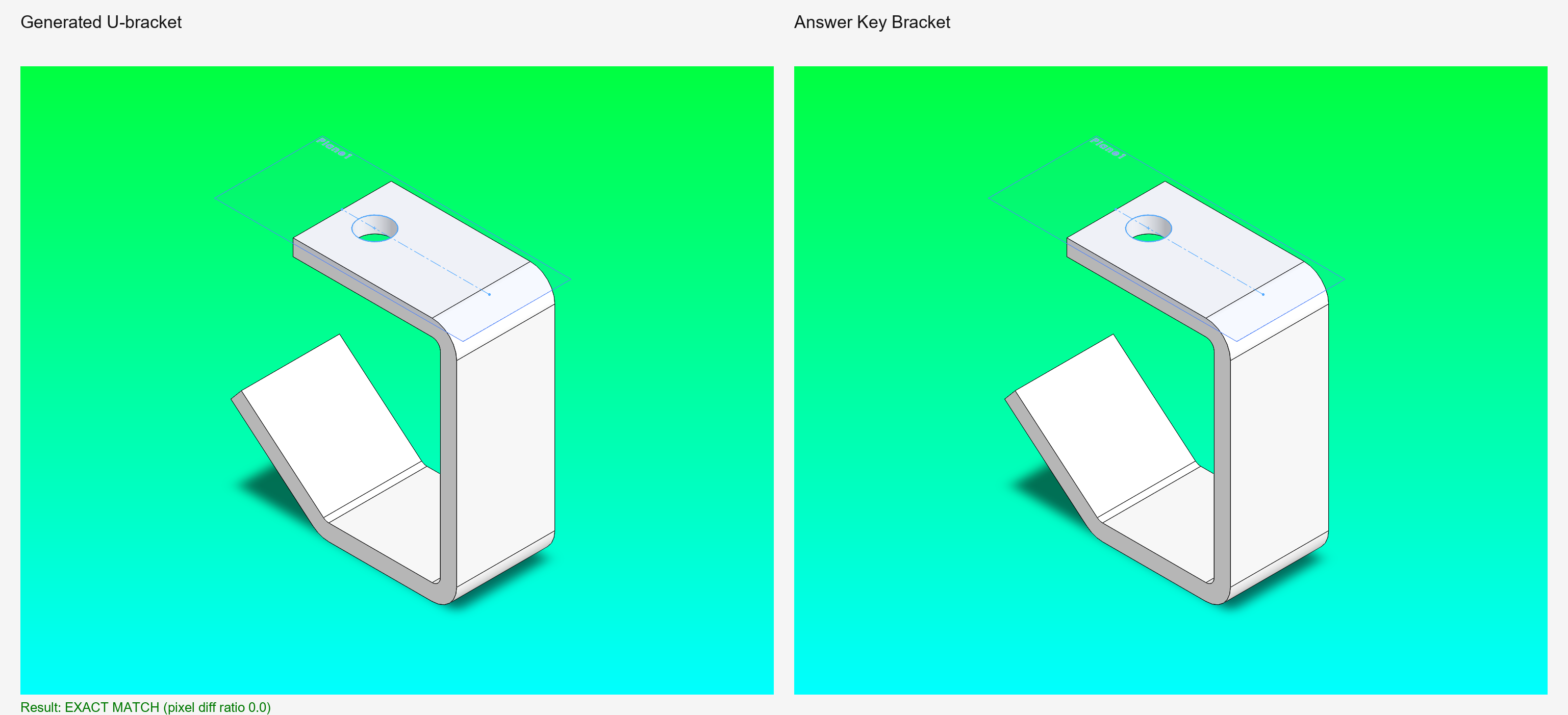
This generates tutorial-parts/u_bracket_from_prompt.SLDPRT and an isometric PNG alongside the SolidWorks answer-key render for visual comparison.
Advantages: - Fast, deterministic output - Repeatable across runs - Full control over feature sequence - Easy to version-control and share
Best for: CI/CD pipelines, automated testing, generating baseline artifacts
Track B: SolidWorks-as-Code (SoC) Export
Best for capturing a live MCP session as a replayable Python script.
After building a part interactively through MCP tool calls, export the session log as a clean script:
from solidworks_mcp.agents.soc_exporter import export_session

export_session(session_id="...", output_path="my_part.py")
The exported script mirrors the structure of build_u_bracket_artifact.py — adapter calls, sketch sequences, extrusion parameters — ready to replay or version-control.
Best for: Capturing design intent, sharing reproducible builds, checkpoint rewind
Choosing Your Track
| Goal | Track | Reason |
|---|---|---|
| Build a known part | A (Script) | Fast, repeatable, CI-ready |
| Capture a live session | B (SoC Export) | Turn interactive work into a script |
| Bulk generation | A (Script) | Automation, minimal overhead |
Available Tutorials
Prompt-Driven Walkthroughs
Smart Dimensions, Reference Points, Save Bodies & Centre Marks
— a live MCP session (real SolidWorks 2026, real screenshots) driving
add_sketch_dimension, create_reference_point, save_body_as_part, and
auto_center_marks entirely from plain-language prompts. Includes the exact
prompt text, the tool calls each one triggers, and the gotchas (origin-plane
picks, entity-ID rules, count read-back).
Reference Artifacts
U-Bracket Build Script — Builds the SolidWorks 2026 sample bracket from measured sketch coordinates; produces .sldprt and isometric PNG
View full script — build_u_bracket_artifact.py
from __future__ import annotations

import asyncio
from pathlib import Path
from typing import Any

from solidworks_mcp.adapters import create_adapter
from solidworks_mcp.adapters.base import ExtrusionParameters
from solidworks_mcp.config import load_config

ROOT = Path(__file__).resolve().parents[3]
ARTIFACT_DIR = ROOT / "docs" / "getting-started" / "tutorial-parts"
OUTPUT_PART = ARTIFACT_DIR / "u_bracket_from_prompt.sldprt"
OUTPUT_IMAGE = ARTIFACT_DIR / "u_bracket_from_prompt_isometric.png"
ANSWER_KEY = Path(
    r"C:\Users\Public\Documents\SOLIDWORKS\SOLIDWORKS 2026\samples\learn\U-Joint\bracket.sldprt"
)
ANSWER_KEY_IMAGE = ARTIFACT_DIR / "answer_key_bracket_isometric.png"


def require(result: Any, label: str) -> Any:
    if not result.is_success:
        raise RuntimeError(f"{label} failed: {result.error}")
    return result


def unwrap_for_method(adapter: Any, method_name: str) -> Any | None:
    current: Any | None = adapter
    visited: set[int] = set()
    while current is not None and id(current) not in visited:
        visited.add(id(current))
        if hasattr(current, method_name):
            return current
        current = getattr(current, "adapter", None)
    return None


def create_cut_extrude_direct(adapter: Any) -> None:
    raw_adapter = unwrap_for_method(adapter, "currentModel")
    if raw_adapter is None or raw_adapter.currentModel is None:
        raise RuntimeError("Could not access raw adapter currentModel for cut fallback")

    model = raw_adapter.currentModel
    feature_manager = model.FeatureManager

    # Blind cut 10 mm from Sketch2 (not through-all).
    feature = feature_manager.FeatureCut3(
        True,
        False,
        False,
        0,
        0,
        0.01,
        0.0,
        False,
        False,
        False,
        False,
        0.0,
        0.0,
        False,
        False,
        False,
        False,
        False,
        False,
        True,
        False,
        False,
        False,
        0,
        0.0,
        False,
    )
    if not feature:
        # Some installs flip the sketch normal on face/offset-plane sketches.
        feature = feature_manager.FeatureCut3(
            True,
            False,
            True,
            0,
            0,
            0.01,
            0.0,
            False,
            False,
            False,
            False,
            0.0,
            0.0,
            False,
            False,
            False,
            False,
            False,
            False,
            True,
            False,
            False,
            False,
            0,
            0.0,
            False,
        )
    if not feature:
        raise RuntimeError("Direct FeatureCut3 fallback returned no feature")


def create_sketch_on_top_planar_face(adapter: Any, sketch_name: str) -> None:
    """Start Sketch2 on a deterministic plane aligned to the top flange face.

    On some COM bindings face-picking is unreliable, so this creates an offset
    plane from Top Plane at the measured top-face elevation (88.90 mm), then
    starts the sketch on that plane.
    """
    raw_adapter = unwrap_for_method(adapter, "currentModel")
    if raw_adapter is None or raw_adapter.currentModel is None:
        raise RuntimeError("Could not access raw adapter currentModel for face sketch")

    model = raw_adapter.currentModel

    top_plane = model.FeatureByName("Top Plane") or model.FeatureByName("Planta")
    if not top_plane:
        raise RuntimeError("Failed to find Top Plane for Sketch2 offset plane")

    model.ClearSelection2(True)
    if not top_plane.Select2(False, 0):
        raise RuntimeError("Failed to select Top Plane for Sketch2 offset plane")

    # swRefPlaneReferenceConstraint_Distance = 8
    offset_feature = model.FeatureManager.InsertRefPlane(
        8, 88.9 / 1000.0, 0, 0.0, 0, 0.0
    )
    if not offset_feature:
        raise RuntimeError("Failed to create top-face offset plane for Sketch2")

    model.ClearSelection2(True)
    if not offset_feature.Select2(False, 0):
        raise RuntimeError("Failed to select Sketch2 offset plane")

    sketch_manager = model.SketchManager
    try:
        sketch = sketch_manager.InsertSketch(True)
    except Exception:
        sketch = sketch_manager.InsertSketch()

    # Some COM variants return bool for InsertSketch; add_* operations only
    # require currentSketchManager, so keep a nullable currentSketch here.
    if isinstance(sketch, bool):
        sketch = None

    if hasattr(raw_adapter, "_reset_sketch_entity_registry"):
        raw_adapter._reset_sketch_entity_registry()

    raw_adapter.currentSketchManager = sketch_manager
    raw_adapter.currentSketch = sketch
    raw_adapter._sketch_count += 1
    raw_adapter._last_sketch_name = sketch_name


def close_all_docs_and_restore(adapter: Any, model_path: Path) -> None:
    """Close open docs and restore the saved tutorial part as active."""
    raw_adapter = unwrap_for_method(adapter, "swApp")
    if raw_adapter is None or raw_adapter.swApp is None:
        raise RuntimeError("Could not access raw adapter swApp for document cleanup")

    app = raw_adapter.swApp
    # Prevent stale PartXXX windows from remaining open between runs.
    try:
        app.CloseAllDocuments(True)
    except Exception:
        # Fallback: best effort close-all by title/path for older COM variants.
        app.CloseDoc(str(model_path))


async def ensure_saved_part_active(adapter: Any, model_path: Path, label: str) -> None:
    """Open the saved part and keep it as adapter/current active model."""
    require(await adapter.open_model(str(model_path)), label)


async def build_part() -> None:
    config = load_config()
    adapter = await create_adapter(config)
    await adapter.connect()
    try:
        require(await adapter.create_part(name="u_bracket_from_prompt"), "create_part")

        # Rebuild the SolidWorks sample bracket from measured sketch coordinates.
        # Feature tree target: Sketch1 -> Base-Extrude-Thin -> Sketch2 -> Cut-Extrude1.
        # Units are mm, derived from the sample model currently shipped with SW 2026.

        require(await adapter.create_sketch("Front"), "create_sketch Sketch1")

        require(await adapter.add_line(0.0, 0.0, 0.0, 82.55), "right web")
        require(await adapter.add_line(0.0, 82.55, -57.15, 82.55), "top flange")
        require(await adapter.add_line(-77.216, 27.494, -44.45, 0.0), "angled tab")
        require(await adapter.add_line(-44.45, 0.0, 0.0, 0.0), "bottom rail")
        require(await adapter.exit_sketch(), "exit_sketch Sketch1")

        # Base-Extrude-Thin: mid-plane 38.1 mm depth, 6.35 mm thin-wall.
        require(
            await adapter.create_extrusion(
                ExtrusionParameters(
                    depth=38.1,
                    thin_feature=True,
                    thin_thickness=6.35,
                    both_directions=True,
                    auto_fillet_corners=True,
                    fillet_corners_radius=3.175,
                )
            ),
            "create Base-Extrude-Thin",
        )

        # Sketch2: place the hole on the top flange face (highlighted sample face).
        # Offset is 12.70 mm from the left edge, diameter is 12.70 mm.
        create_sketch_on_top_planar_face(adapter, "Sketch2")
        require(
            await adapter.add_centerline(0.0, 0.0, -57.15, 0.0),
            "Sketch2 flange reference centerline",
        )
        require(await adapter.add_circle(-44.45, 0.0, 6.35), "sample bracket hole")
        definition_check = require(
            await adapter.check_sketch_fully_defined("Sketch2"),
            "check_sketch_fully_defined Sketch2",
        )
        if isinstance(definition_check.data, dict):
            is_defined = definition_check.data.get("is_fully_defined")
            if is_defined is False:
                print(
                    f"WARNING: Sketch2 may not be fully defined: {definition_check.data}"
                )
        require(await adapter.exit_sketch(), "exit_sketch Sketch2")

        create_cut_extrude_direct(adapter)

        require(await adapter.save_file(str(OUTPUT_PART)), "save_file tutorial part")
        await ensure_saved_part_active(
            adapter, OUTPUT_PART, "activate tutorial part before screenshot"
        )
        require(
            await adapter.export_image(
                {
                    "file_path": str(OUTPUT_IMAGE),
                    "format_type": "png",
                    "width": 1600,
                    "height": 1000,
                    "view_orientation": "isometric",
                }
            ),
            "export_image tutorial part",
        )

        if ANSWER_KEY.exists():
            require(await adapter.open_model(str(ANSWER_KEY)), "open answer key")
            require(
                await adapter.export_image(
                    {
                        "file_path": str(ANSWER_KEY_IMAGE),
                        "format_type": "png",
                        "width": 1600,
                        "height": 1000,
                        "view_orientation": "isometric",
                    }
                ),
                "export_image answer key",
            )

        # Keep only the rebuilt bracket active at end of run.
        # close_all_docs_and_restore(adapter, OUTPUT_PART)
        await ensure_saved_part_active(adapter, OUTPUT_PART, "restore tutorial part")
    finally:
        await adapter.disconnect()


if __name__ == "__main__":
    ARTIFACT_DIR.mkdir(parents=True, exist_ok=True)
    asyncio.run(build_part())
    print(OUTPUT_PART)
    print(OUTPUT_IMAGE)
    print(ANSWER_KEY_IMAGE)
Guided Prompt Packs
U-Joint Rebuild Prompts — Pre-written prompts for rebuilding the U-joint if you already have reference samples
View full prompt pack — u_joint_rebuild_prompt.md
U-Joint Rebuild Prompts
Note: These prompts are for when you have access to the reference SolidWorks sample models and want to match them exactly. For learning and from-scratch builds, start with the U-Joint Assembly Tutorial instead.
Reference models location:
Reference Model Analysis
Before using these prompts, inspect the reference assembly to understand the geometry:
bracket.sldprt— Mounting baseYoke_male.sldprt— Primary yoke armYoke_female.sldprt— Secondary yoke armSpider.sldprt— Cross hub connecting yokesPin.sldprt— Shaft pin (qty 4 in assembly)Crank_shaft.sldprt— Drive shaftCrank_arm.sldprt— Actuation leverCrank_knob.sldprt— Grip handleUJoint.SLDASM— Complete assembly
Prompt 1: Bracket (Exact Parity)
Use this prompt if you want to match the reference bracket exactly and keep the same feature-tree shape.
Create Bracket_v1.SLDPRT from scratch to match the reference model exactly.

Use mm units and do not add extra features.

Required feature tree:
1. Sketch1
2. Base-Extrude-Thin
3. Sketch2
4. Cut-Extrude1

Build steps (exact dimensions):
1. On Front Plane, create Sketch1 using these connected line segments:
   - (0.00, 0.00) to (0.00, 82.55)
   - (0.00, 82.55) to (-57.15, 82.55)
   - (-57.15, 82.55) to (-77.216, 27.494)
   - (-77.216, 27.494) to (-44.45, 0.00)

   Add dimensions to ALL lines, ensure all sketches are fully defined before moving on.
   Ensure the first and last points are NOT connected, it's an open u-bracket design.

2. Create Base-Extrude-Thin:
   - Mid-plane depth: 38.10
   - Thin wall thickness: 6.35
   - Auto-fillet corners ON
   - Corner radius: 3.175

3. Create Sketch2 on the top planar face (offset plane from Top Plane at 88.90 if needed).

4. In Sketch2:
   - Add centerline from (0.00, 0.00) to (-57.15, 0.00)
   - Add circle centered at (-44.45, 0.00) with diameter 12.70

5. Create Cut-Extrude1:
   - Blind cut depth: 10.00

Validation requirements:
- Report final feature tree names in order.
- Export isometric PNG as bracket_isometric.png.
- Compare against reference bracket isometric and report mismatch status.

Save the part as Bracket_v1.SLDPRT.
Verification snapshot from this run:
Prompt 2: All Yoke Parts (Exact Parity)
Create Yoke_male.SLDPRT and Yoke_female.SLDPRT from scratch to match the reference models exactly.

Reference models:
- C:\Users\Public\Documents\SOLIDWORKS\SOLIDWORKS 2026\samples\learn\U-Joint\Yoke_male.sldprt
- C:\Users\Public\Documents\SOLIDWORKS\SOLIDWORKS 2026\samples\learn\U-Joint\Yoke_female.sldprt

Steps:
1. Inspect the reference yoke parts and extract geometry, dimensions, and feature sequence
2. Build Yoke_male.SLDPRT with exact feature tree and dimensions
3. Build Yoke_female.SLDPRT (may be identical or slightly different)
4. Replicate appearance and material properties
5. Validate: Report feature tree for each yoke and confirm they match reference models

Export isometric PNG for each: Yoke_male_isometric.png and Yoke_female_isometric.png
Prompt 3: Spider and Pin
Create Spider.SLDPRT and Pin.SLDPRT from scratch to match the reference models exactly.

Reference models:
- C:\Users\Public\Documents\SOLIDWORKS\SOLIDWORKS 2026\samples\learn\U-Joint\Spider.sldprt
- C:\Users\Public\Documents\SOLIDWORKS\SOLIDWORKS 2026\samples\learn\U-Joint\Pin.sldprt

Steps:
1. Inspect reference parts and extract exact dimensions and feature sequences
2. Build Spider.SLDPRT: cross-shaped hub with four radial bores for pins
3. Build Pin.SLDPRT: cylindrical shaft with head flange
4. Match all critical dimensions and tolerances
5. Validate: Report feature tree for each part

Export isometric PNG for each: Spider_isometric.png and Pin_isometric.png
Prompt 4: Crank Parts (Shaft, Arm, Knob)
Create Crank_shaft.SLDPRT, Crank_arm.SLDPRT, and Crank_knob.SLDPRT from scratch to match reference models exactly.

Reference models:
- C:\Users\Public\Documents\SOLIDWORKS\SOLIDWORKS 2026\samples\learn\U-Joint\Crank_shaft.sldprt
- C:\Users\Public\Documents\SOLIDWORKS\SOLIDWORKS 2026\samples\learn\U-Joint\Crank_arm.sldprt
- C:\Users\Public\Documents\SOLIDWORKS\SOLIDWORKS 2026\samples\learn\U-Joint\Crank_knob.sldprt

Steps:
1. Inspect all three crank parts and extract geometry
2. Build Crank_shaft.SLDPRT with drive flange and mounting holes
3. Build Crank_arm.SLDPRT with connection bore and grip section
4. Build Crank_knob.SLDPRT with sphere body and connection post
5. Match all critical dimensions
6. Validate: Report feature tree for each part

Export isometric PNG: Crank_shaft_isometric.png, Crank_arm_isometric.png, Crank_knob_isometric.png
Prompt 5: Assembly Build (Exact Parity)
Create UJoint.SLDASM from scratch to match the reference assembly exactly.

Reference assembly: C:\Users\Public\Documents\SOLIDWORKS\SOLIDWORKS 2026\samples\learn\U-Joint\UJoint.SLDASM

Steps:
1. Inspect reference assembly: component tree, mate list, DOF constraints
2. Insert all 8 parts (or required qty) with exact mate sequence
3. Replicate every mate (coincident, concentric, distance, angle, etc.)
4. Validate final assembly:
   - All parts present in correct locations
   - All mates fully defined (no under-constraint)
   - No over-constraint
   - No interference between parts
   - Mechanism articulates smoothly (if applicable)
5. Report:
   - Total mate count and types
   - Interference analysis
   - Motion summary (free DOF, constrained DOF)

Export isometric PNG of final assembly.
Prompt 6: Final QA and Parity Check
Perform final parity check between your generated parts/assembly and the reference UJoint.SLDASM.

Checklist:
- [ ] All 8 parts exist and are correctly named
- [ ] Each part feature tree matches reference model
- [ ] Assembly has all required mates
- [ ] Assembly is fully defined
- [ ] No interference detected
- [ ] Crank shaft and driven components articulate correctly
- [ ] All dimensions within ±0.5% of reference models
- [ ] Material properties match (if specified)
- [ ] Appearance/color matches reference (if specified)

For any mismatches:
- Identify which part or mate differs
- Report the specific deviation
- Provide corrective action (re-build part, adjust mate, etc.)
- Re-validate after correction

Generate final pass/fail report with images (isometric view from 3 angles).
When to Use These Prompts
Use these prompts if:
- You want to match the exact SolidWorks reference sample
- You're validating MCP tool accuracy against known geometry
- You need a precise baseline for comparative testing
Use the U-Joint Assembly Tutorial if:
- You're learning MCP and the Prefab UI workflow
- You want to build from scratch without reference constraints
- You want to modify dimensions for your application
- You're designing a custom U-joint variant
Related
Getting Started
Run the reference artifact to verify your MCP setup is working:
A successful run produces tutorial-parts/u_bracket_from_prompt.SLDPRT and two PNG images.